Determine the Voltage V1 in the Circuit.
Asked Mar 6 2020 in Electronics by Richa01 535k points operational amplifiers. Solution for Calculate the output voltage for the given circuit if V1 25 V and V2 225 V.
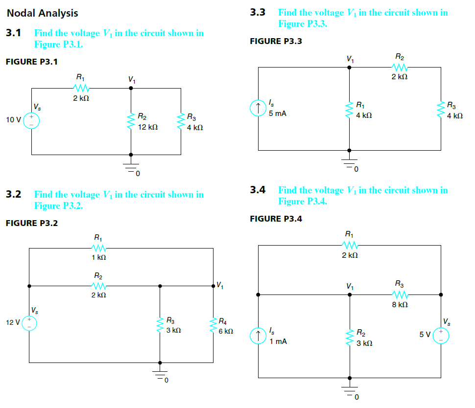
Solved Nodal Analysis 3 3 Find The Voltage V1 In The Circuit Chegg Com
Solution for Determine the output voltage V1 of the given circuit.

. If you know voltage you calculate the current. 653 if the battery is rated at V batt equal to a 9 V. C Verify your solutions with appropriate simulations.
Experts are tested by Chegg as specialists in their subject area. Your equation is. So thats the whole game over here.
08V 29 ia 10kΩ 500Ω ia V1 152V 20002 25V Figure 2 12 marks. P 42-2 Determine the node voltages for the circuit of Figure P 42-2. Homework Equations The second law of Kirchhoff states that the sum of all voltajes must equal 0 The Attempt at a Solution I found in the book that the solution is V1.
Asked Mar 6 2020 in Electronics by Richa01 535k points operational amplifiers. Electrical Engineering questions and answers. V1 -16V.
Taking the outer closed loop ABCDEFA and applying KVL to it we get. 10V R1 1002 V1 R2 1002 V2 R3 1002 V3 R4 1002 ww ww ww. R 12 Ω v1 4 V and v2 28 V.
Who are the experts. Calculate output voltage if V1 300 mV V2 700mV. P 45-2 The values of the mesh currents in the circuit shown in Figure P 45-2 are i1 2 A i2 3 A and i3 4 A.
However the current can be different on each path. 3D 3D 10 V 5 kn -10 V 5 kn 5 kn 10 V 500 n 5 kn -10 V 10 Answered. Voltage Resistor R2 9V.
1 dfrac V_1 6kdfrac V_1-V_2 4k6m4mcolor orange text. Determine the values of the resistance R and of the voltages v1 and v2 of the voltage sources. Electrical Engineering questions and answers.
For the circuit shown in figure determine the unknown voltage drop V1. I_1 I_2 I 1. Voltage Resistor R1 9V.
Calculate the output voltage if V1 -02V and V2 01V. One may think of Kirchhoffs laws or mesh analysis etc. But a little thought will show that the question can be solved by the simple application of Kirchhoffs voltage law.
- 16 x 3 - 4 x 2 40 - V1 0. V 1 2 V v 2 30 V and v 3 24 V Figure P 42-2 Write a voltage node equation at v 1 𝑨 𝒗 𝒗 𝛀 𝒗 𝛀 Multiply equation by 20 Ω and we get 𝑽𝒗 𝒗 𝒗 𝒗 𝒗 𝑽 Write another voltage node equation at v. Calculate the output voltage for the bartleby.
On the right you also have a current flowing out of node 2. V 1 5 0 m V sin 1 0 0 0 t V_ 1 50 mV sin 1000t V 1. V 1 6 k V 1 V 2 4 k 6 m 4 m e q.
If you know the current you calculate the voltage. Calculate the voltage V 1 as labeled in the circuit of Fig. V 2 1 0 m V sin 3 0 0 0 t V_ 2 10 mV sin 3000t V 2.
We review their content and use your feedback to. Determine the voltage V1 and the output voltage V in the circuit below. 30 v 1 1 -5 V - 3 V.
14V I tried to solve V1 by adding 9. In this case the voltage is the same in both paths of the parallel circuit. Determine the voltage v1 in terms of the supply voltage vs for the circuit shown in the figure Where C 4 Ω D 4 Ω E 4 Ω and F 2 Ω.
Homework Statement Given the following circuit find the values of V1 and V2. B By using Ohms and Kirchoffs laws determine the voltage V1 in the circuit shown in Figure 2. 4kΩ 2kΩ w a 15 ΚΩ 5kΩ w V1 Vo 5V 3 1mA 1 10 kΩ Stage 1 amplifier Stage 2 amplifier.
1 v2120 v2-v18 node 2 On the left you have currents flowing out of node 2. 2 V - 1 V - sov. 50mV sin1000t and.
And the 6mA leave the node 4mA is coming into the node We can express these currents in terms of voltage and resistance using IVR. And now that I know the voltage again apply Ohms law this time to calculate the current. Knowing that we can determine the voltage drop without doing any calculations for resistors R1 and R2 as we know the total voltage of the circuit.
Its a little shabby but hopefully the color helps you identify or differentiate between them. If its on the right and it must balance the currents on the left it should be flowing INTO node two. Commenting on the possible origin of any discrepancies.

Solved Consider The Circuit Shown In Figure 1 Suppose Chegg Com

Find The Node Voltages V1 And V2
Find The Unknown Voltage V1 In The Circuit Of Fig Sarthaks Econnect Largest Online Education Community
Comments
Post a Comment